Build A 555 Noise Maker With Electric Paint

Learn how to use a 555 timer and an Electric Paint potentiometer to make an interactive noise-maker.
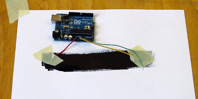
In this tutorial we will build a simple circuit that uses a 555 timer and an Electric Paint potentiometer to make an interactive noise-maker. Before you dive into this tutorial it is worth checking out one of Matt’s tutorials on building a potentiometer using Electric Paint. It’s a good introduction to painted potentiometers, but not essential if you don’t have an Arduino. Also, if you are new to the 555 timer and are interested in playing around some more with this little chip, check out one of our earlier tutorials here.
By the end of this tutorial you should have a working 555 noise maker circuit connected to a potentiometer made from paper and Electric Paint. You will be able to change the sound coming out of the speaker by changing the position of the slider on the painted potentiometer. By varying the resistance you change the pitch of the sound.
Like in some previous tutorials we will need to connect to the paint again from our breadboard. Previously we used paperclip wires, but this time we are going to try something else… We are going to use a bulldog clip to connect more securely to the paint and use two “slider wires” to vary the position on the painted strip. The bulldog clip wire is assembled in much the same way as a paperclip wire, but you can refer to the pictures below which show how this can be done with stranded wire and some solder.
We love it when you share your projects! Post your project on Instagram, YouTube, or Twitter, and make sure to tag @bareconductive or use #bareconductive. You can also send your videos and photos to info@bareconductive.com so we can post them on our site for the world to see.
Materials To begin you will need:
- 1 x Electric Paint 50ml
- 1 x Paintbrush
- 2 x Paper
- 1 x 555 Timer
- 1 x Resistor
- 1 x Stranded Wire
- 1 x Jumper Wires
- 1 x Breadboard
- 1 x Speaker
- 2 x Capacitors
- 1 x 9V Battery
- 1 x Battery Clip
- 1 x Bulldog clip
- Copper Tape
- Soldering Kit
Step 1 Gather your Materials
The first step is to gather the appropriate materials mentioned above:
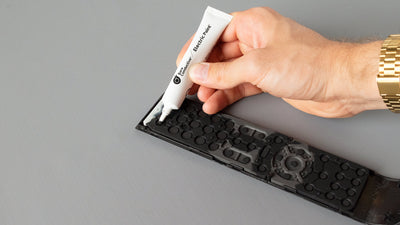
A jar of Electric Paint, paint brush and paper, or an Electric Paint Tube
A 1K Ohm resistor
Two electrolytic capacitors around 0.68uF (0.68uF = 680nF = 680 000pF) this value is now critical. We had a couple at this value lying around. 1uF will work too – play around with the values you have at hand.
A small speaker or piezo transducer
A 555 timer IC (we are using the LM555CN by siemens)
Some wire and a bulldog clip to make your bulldog connector wire
Solder-less breadboard and some jump wires
Some paper or other non-conductive material to apply the Electric Paint
A 9V Battery and a battery clip with wires
Step 2 Painting the Potentiometer
The most basic way to think of a potentiometer, or variable resistor in this case, is a long piece of conductive material that can be tapped off with a slider at different lengths. In our case the material is Electric Paint and our slider is simply a long piece of wire. Depending on what length you want to ‘tap off’ from the painted line you can vary the resistance across the potentiometer. The longer the painted piece you ‘tap off’ the higher the resistance. So go ahead – paint a long thin line and add a small square at the start to make it easier to connect our bulldog clip wire. This is our painted variable resistor.

Step 3 Making a bulldog wire connector and a slider
Taking your piece of wire, cut two sensible lengths of about 30 – 40 cm each and strip the ends with a pair of wire cutters or wire strippers. Taking a wire solder one of its ends to your bulldog clip and use the other end to place on your breadboard (see schematic). This wire will be used to connect to the base of your painted potentiometer. This is our bulldog clip wire.
Take the other wire and connect one end to your breadboard (see schematic) and leave the other end free for sliding. We can simple use the exposed end of the wire to make contact with the paint and generate noise.

Step 4 Circuit Diagram and Breadboard Schematic
Now its time to get the technical bit sorted. Take you components and connect them on your breadboard. Make sure to double-check your connections using the circuit diagram and breadboard schematic below. You can use this while you follow along in the tutorial video, pausing the video when you need to get a closer look at which tracks are being connected. You can download the 555 breadboard schematic here and the 555 circuit diagram here.
Step 5 Connecting the Circuit
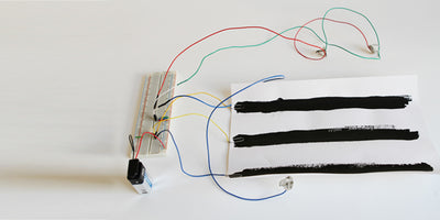
If you followed the schematic closely your breadboard should look quite similar to the one pictured here. Take a good look at the breadboard schematic and make sure you have connected the circuit up correctly.
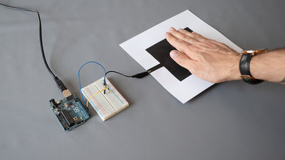
Step 6 Attaching the Bulldog Clip Wire and Making Noise with your Finger
Now that you have all the separate parts ready its time to synthesize everything into a working noise maker!
Take the bulldog clip wire and attach it to your connection pad at the start of your line, which you painted earlier. Next, take your slider wire and run it along the painted line.
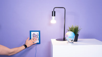
By moving the slider across the painted line you can vary the frequency of the sound coming out of the speaker! If you have some copper tape lying around you can stick the exposed metal of your slider wire onto your finger for a more natural interaction with the paint.

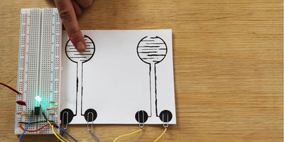
Step 7 Completed Circuit and Beyond!
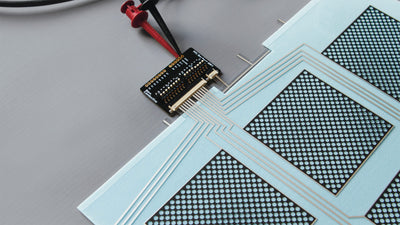
You can now make some awesome (or annoying) sounds and design even more interesting painted potentiometers too. Try using vinyl cutouts as stencils or even try screen printing if you have access to the equipment. Make sure to send in photos or videos of you having fun with this circuit so we can post it on our community wall. Below is an example of a painted variable resistor made using a vinyl cutout as a stencil.