Make A Simple LED Switch With Electric Paint

Create a touch-sensitive circuit with Electric Paint and a 555 timer to control the state of an LED
In this tutorial, we will make a simple touch sensitive circuit using some Electric Paint, a 555 timer circuit, a couple of resistors, a LED and a capacitor. The 555 timer is a fun and versatile integrated circuit (IC) that can be used in several distinct ways. There are loads of interactive circuits that can be made with this chip, we’ll be adding tutorials illustrating more of these projects in the future. Today we are using the 555 with its internal flip-flop to sense the change in voltage at two inputs in the circuit. Luckily you don’t need to know what’s happening inside the chip to enjoy the interactions that it affords!
When you touch the Electric Paint on either side of the gap you connect the circuit through your skin – don’t worry, the current is so low you will not be able to notice it. The 555 timer senses voltage change at pin 6 and pin 2, depending on which button you press, and flips the output state at pin 3 – turning the LED ON or OFF. By the end of this tutorial you will have painted two touch buttons, with Electric Paint Jar or Pen, that connect to a touch sensitive ON/OFF 555 timer circuit. Once you have got this simple circuit going you are free to get even more creative in using the paint to make different graphical touch buttons. Please send your electro-art works to us to put up on the Make page!
We love it when you share your projects! Post your project on Instagram, YouTube, or Twitter, and make sure to tag @bareconductive or use #bareconductive. You can also send your videos and photos to info@bareconductive.com so we can post them on our site for the world to see.
You will need:
- 1 x Electric Paint 50ml
- 1 x Paintbrush
- 1 x 350 gsm Paper
- 1 x LM555 Integrated Circuit
- 5 x Resistors
- 1 x Bread Board
- 7 x Jumper Wires
- 3 x Capacitor
- 1 x LED
- 4 x Paper Clip Wires
- 1 x 9V Battery
- 1 x Battery Clip
- 1 x 555 Timer
- 1 x Breadboard
Step 1 To make this nifty circuit you will need:
A jar of Electric Paint, paint brush and paper, or an Electric Paint Pen
A 330 Ohm resistor, two +-2.7 Mega Ohm resistors (make sure it is sufficiently large for greater sensitivity), one 10nF capacitor (0.01uF = 10nF = 10 000pF) and a LED
Some wire to make your paperclip wire connectors
Solder-less breadboard and some jump wires
Some paper or other non-conductive material to apply the Electric Paint
A 9V Battery and a battery clip with wires.
- 555 Timer
- 330 Ohm Resistor
- 2.7 M Ohm Resistor
- 10nF Ceramic Capacitor
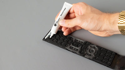
Step 2 Painting the On/Off Touch Buttons
Before you start to paint your buttons onto a non-conductive surface, such as paper, think about what form you would like the graphic to take. You can think of the ‘button’ as a line of paint with a gap and at that gap you connect the circuit with your finger, thumb or other body part. So make sure it is narrow enough for this. A very small current, imperceptible to a human, flows through the paint and across your skin when you bridge the circuit over the paint-gap.
Step 3 Design your Graphic
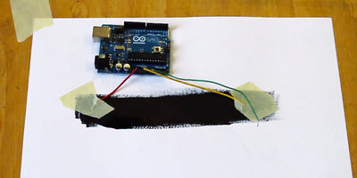
Second, paint your decided button graphic onto your surface with Electric Paint and a paintbrush. I have done this on paper and used a thin piece of masking tape to ensure a clean thin break at my touch points. Below is my finished pair of touch buttons after being left to dry for several minutes. I have made sure that the starts of my lines come close to the edge of the paper so that they can be reached by a paperclip.
Step 4 Placing the Components and Connecting the Circuit
The next step is to assemble the simple circuit (pictured on right). Take a good look at the breadboard schematic and make sure you have connected the circuit up correctly. You can download a copy of the breadboard schematic here and a copy of the circuit diagram here.

Step 5 Adding the Paperclip Wires
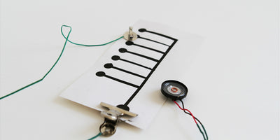
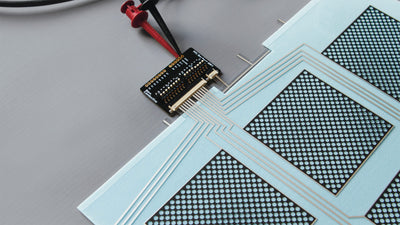
Once you have your circuit setup on your breadboard you can place your paperclip wires in the tracks indicated in your schematic and in the images below. Take a look at our connecting tutorial which shows you how to make these cool prototyping wire – and other interesting ways to connect to Electric Paint.
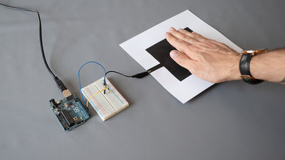
Step 6 Testing
You can test it by first touching the blue paperclips together to turn the LED ON and then touching the yellow pair together to turn it OFF.

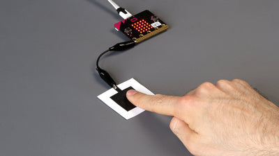
Step 7 Connecting to Electric Paint
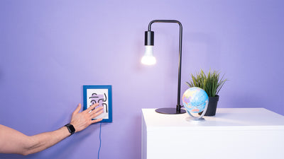
Now you can connect them to your touch buttons using the paperclip ends of the wires. Connect the blue wires to your ON touch button and your yellow wires to your OFF touch button. You can simply place your finger, thumb or other body part at the gap to control you LED! It’s that simple and ultimately very satisfying!

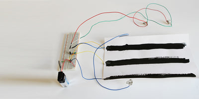
Step 8 Completed Circuit!

Step 9 Troubleshooting
If this is working for you, you can now start experimenting with creating more interesting painted buttons with your paint – they don’t even need to look like buttons. Try using vinyl cutouts as stencils or even try screen printing if you have access to the equipment.