Light Up Board Design details, more than meets the eye

The Light Up Board is made to be easy to use, but has some surprising hidden features
Following our successful Kickstarter and Indiegogo campaigns, we are launching the Light Up Board as a standalone product, making it available separately from the Electric Paint Lamp Kit. This way, you will have the option to use light in different concepts and projects.
As part of this process, we sat down with two of our engineers and designers, Stefan and Owen, for an interview to give you an insight into Bare Conductive’s thought and the working process behind the Light Up Board design. We hope that you find this interview interesting and that it gives you an understanding of the design choices we made in making the Light Up Board.
Why did Bare Conductive design the Light Up Board?
Stefan: There are two aspects to this question; why we wanted to work with light and why we designed the Light Up Board.
When we were designing the Electric Paint Lamp Kit, we wanted to give our users a project that helps them understand our Electric Paint in the context of electricity. For many people, light is shorthand for electricity, and we aimed to explain how our paint can be used as a part of an electrical circuit, which can be relatively complicated. By having light as an output, it makes the idea more tangible, so that’s why we chose light.
We designed the Light Up Board as a way to give people a variety of different projects to work and experiment with, even if they didn’t have any particular technical confidence. So they could play with light, without having to know how it works first.

Why is it so important for the Light Up Board to connect to paper?
Owen: The Light Up Board design aims to complement the capabilities of Electric Paint. Paper is an excellent material to paint onto because it is at the heart of many people’s projects or processes. Many start with paper models for lots of different projects, even if they eventually make it out of wood or metal. But a lot do projects just on paper because it is low cost, and it can allow very high precision.
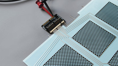
The twist and lock connecting mechanism of the Light Up Board is an essential aspect of its design because we think the biggest problem that the printed electronics industry has to solve is connectors. If we’re telling people that you can paint Electric Paint onto paper, plastic, or wood, then we need to also show them how to make a mechanical and an electrical connection. So the Light Up Board is a unique response to that, because from the user’s perspective, they don’t need any tools to make the connection happen. But it also doesn’t require us to add a complicated component to the board, and the user can easily modify their project a lot.
Why is the board non-programmable?
Stefan: We wanted to create a product that was accessible to someone that doesn’t have any technical expertise. In some way, the board is programmable; it’s just not programmed by using a computer. You can change its behaviour, but if someone needs something that is entirely programmable then the Touch Board is a better alternative. The Light Up Board is an introduction to the technology of the Touch Board, and its a usable, practical light source. By changing the connections, you can set it into one of the six different modes. There are ways to reprogram the board with a computer, but that wasn’t the goal of the design. The goal was to give people the least abstract way to understand how the paint works.
Why does the Light Up Board come with 6 different modes?
Stefan: We chose three primary modes and the other three modes are bonus modes. When you look at the capacitive sensors, they can either act as a button or as a control switch. So that gave rise to the touch and proximity mode, respectively. Then we asked the question: What happens if we put multiple buttons in a row, and what kind of lighting interactions would that create? The result is the dimmer mode. These three modes that we chose were based on trying to develop three useful, exciting lighting projects, that also exposed more people to our technology.
The spinning mode was initially the ‘error’ mode, so we could tell our users that the board wasn’t working as expected. But we thought it was quite fun and wanted to make it controllable, so we added it as a bonus mode, so people could use it for things like wearables. The candle mode seemed like an obvious step on from the touch lamp, though it needed a lot of hard work to make it look realistic. We implemented the dice mode because we wanted to include something else that was playful in the Light Up Board design.

What is the output light colour temperature and why did you choose that one?
Stefan: Firstly, to give you some context of the spectrum, 1850K is the warm temperature of a candle flame, while traditional LEDs are quite blue, in the 6500 – 9500K range. We tried three different light temperatures for the Light Up Board, and for our needs 4000K worked the best.
When you put a neutral 4000K light on white paper, it doesn’t distort the colour. Other temperatures can look very yellow against a white background. Some would say that anything between 2700K and 3000K is more suitable for a gentle mood lamp. But it’s easier to take a very neutral light and tint it, to either soften it or make it harsher with coloured filters or reflectors, than it is to take a warm light and make it a neutral light.
Why did Bare Conductive apply for a patent for the Light Up Board's twist and lock mechanism?
Owen: We wanted to create something that could connect capacitive sensors easily to paper. The initial concept was to look for things already on the market, like a proprietary connector, that could do this job, but there was nothing suitable. We realised that we had to build a connector that lets people do their project wherever they want, and on whatever they want. That was really important. We had the option of going with a flat flex connector, but if we had used this connector, it wouldn’t have allowed people to be very creative.
Whenever you have a connector, like a flat flex connector, it can be fiddly, easily snapped off and it’s not something that people easily understand if they are outside electronics. But also, if you use such a connector, you always have to lift it and fit it in, whereas, with the Light Up Board’s twist and lock mechanism, the board lifts itself and tucks into a similar plane of the substrate, without having to come up the sharp edge. You are using the force from the substrate to create the contact. So it’s the paper itself in combination with the board that’s forming the electrical contact. That’s what the patent is about.
What makes the Light Up Board compelling is that the board itself is the connector for the sensors – there isn’t a connector that is mounted on the board. Because the board is the connector, it’s a more integrated solution, which then means that the board is intimately part of the project. When we considered an off-the-shelf connector, like a flat flex connector, the board would have never really been at the centre of someone’s project; it would have to be an awkward implementation. So it’s not just the electrical connection that’s important, it’s also the mechanical connection.
What was the design process like?
Owen: There was a lot of testing with prototype forms in the Light Up Board design. The limitations of CAD software make it very hard to simulate the behaviour of paper. So the design was something that required proof of principle, which means that you have to physically make it, even in prototype form, to have some answer to whether it’s something that’s worth pursuing. We could have invested resources into expensive simulation software, but if you can quickly make something, test it and see whether it works or not, then that’s much more valuable. It’s found in all areas of design.
There was something interesting in the process about the speed of development and unanticipated learnings. Moving from a CAD design to a physical one, feeding those insights back into CAD and then repeating this cycle is a perfect way to find things we usually wouldn’t have seen if we had just used one tool.
Why is the Light Up Board black with gold plated electrodes?
Owen: Our branding is monochrome, so it was pretty clear the choice was going to be either black or white. We preferred the contrast of a black PCB on white paper, which highlights the board more as a feature. We use gold in the Light Up Board design because of tarnishing. Most PCB plating tarnishes over time, whereas gold plating doesn’t. It’s also easier to wipe clean, and, well, it looks great!
Why are the electrodes not numbered numerically?
Stefan: The electrode numbering relates to the pinout of the chip. We kept the layout simple, to get the best performance and the orientation of the chip. The electrodes happen to line up so that the electrodes on the chip fan out in a slightly counterintuitive way. The naming was kept in case anybody wanted to use the design and work with it in the future. The naming was referenced from the numbers on the chip, instead of adding another numbering system to the Light Up Board design that didn’t have context. It was also numbered to relate to the electrodes of the Pi Cap or Touch Board, as the Light Up Board uses the same capacitive sense chip and is now part of that family.
Thank you very much to Stefan and Owen for explaining about the Light Up Board design! It will be available soon, but if you’d like to be one of the first to get it before it sells out, you can pre-order it on our website from today.
Stay connected with Bare Conductive. Follow, like and comment on Facebook, Twitter & Instagram.