Make a RGB LED Colour Slider with Electric Paint

Physically control an RGB LED by making Electric Paint Potentiometers
In this tutorial, we will build a physical RGB (red, green, blue) LED (light emitting diode) color mixer. Each RGB LED has three internal light emitting diodes (LEDs) for each of the colors – red, green and blue. Further there is a lead to connect and control each of these internal diodes. Thus you can mix these three and get a whole range of new colors.
We love it when you share your projects! Post your project on Instagram, YouTube, or Twitter, and make sure to tag @bareconductive or use #bareconductive. You can also send your videos and photos to info@bareconductive.com so we can post them on our site for the world to see.
Materials To begin you will need:
- 1 x Electric Paint 50ml
- Paintbrush
- Paper
- RGB LED (common anode) - if using common cathode please modify circuit diagram
- Resistor
- Jumper Wires
- Breadboard
- 9V Battery and Battery Clip
- Soldering Kit
- Paperclip Wires and Paper binder Wires (use stranded wire, solder and basic stationary components to make these highly useful connectors)
Step 1 RGB LED Internal Diagram
The diagram on the right shows what one would commonly find inside a RGB LED.
You can see that pin 2 is the three internal LEDs negative lead or cathode and 1, 3 and 4 are each of their respective positive leads or anodes.
We are going to physically control the RGB LED by making Electric Paint Potentiometers for each of its positive leads instead of using static resistors. Thus by altering the resistance we will ultimately change the current flowing into each diode and affect its brightness. This is a fairly crude way to control LEDs. There is a more elegant way to do this using an Arduino and PWM (pulse width modulation). We will cover this in another tutorial.
Step 2 Components
The image on the right shows a RGB LED with a common cathode. This simply means that the 3 internal LED's share a common lead and this lead should be connected to ground. Ground is a name electronically minded folk use as the reference point that all the other voltages are measured from, or a common return path for electric current. In our circuit ground simply means the negative terminal on the 9V battery.
Step 3 Overview
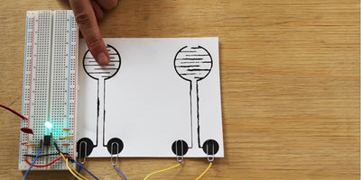
The most basic way to think of a potentiometer, or variable resistor in this case, is a long piece of conductive material that can be tapped off with a slider at different lengths. In our case the material is Bare Paint and our slider is simply a long piece of wire. Depending on what length you want to 'tap off' from the painted line you can vary the resistance across the potentiometer. The longer the painted piece you 'tap off' the higher the resistance.
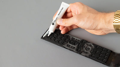
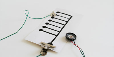
Step 4 Painting the 3 Variable Resistor Strips
Taking your pot of Bare Paint, lavishly paint three lines across a piece of paper or another non-conductive surface. Make sure to bring the lines close to the edge as we will need to connect to the paint using electrical wire and paperclips. Once you have painted your lines, leave them to dry for several minutes. You can leave the paint under a hot light to speed up the drying process.

Step 5 Making Paperclip Wires and Sliders for your Painted Variable Resistor
Taking a piece of stranded wire, cut 3 sensible lengths of about 15 – 20 cm each and strip the ends with a pair of wire cutters or wire strippers. Next, connect the paperclips to one end of each wire. Have a look at this tutorial on how to make paperclip wires in more detail. You will use these paperclip wires to connect from your breadboard to your painted variable resistors.
Next, cut three lengths or about 40 – 50 cm each; you'll need the extra length for freedom of movement. Strip the ends and this time solder paper binders onto one of the ends of each wire. The other end will be placed on the breadboard.\

Step 6 Breadboard Schematic
Now that you have all the separate pieces ready we can connect everything together on the breadboard. Make sure to double-check your connections using the breadboard schematic.

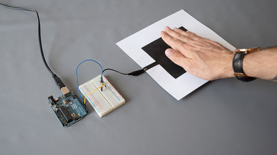
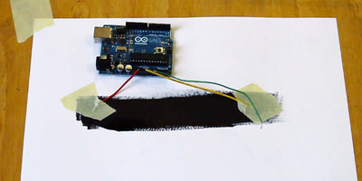
Step 7 Testing the Red, Green, and Blue internal LEDS

Step 8 Touching with the RED Slider
Everything should now be connected, as shown in the photo above. To test the internal LEDS, touch the slider wires on the different strips of paint. Each slider wire should correspond to one internal LED.

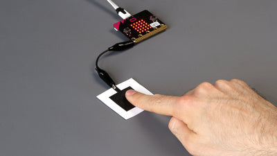
Step 9 Now for Mixing
Its time to experiment and see what colors you can generate. Have fun and send us you photos and comments.