Building an Interactive Wall with Artist Ian Barnard

Collaboration is at the core of Bare Conductive, and it powered the launch of our Interactive Wall Kit
One of the best parts of having an active and engaged community is that we get to collaborate with some incredibly talented people. A couple of months ago, as we began preparations for the launch of our latest product, the Interactive Wall Kit, we found ourselves looking for someone to help us build the very first interactive display using our new technology.
We reached out to a few members of our community who’d created amazing content for us in the past and found that our friend Ian Barnard was keen to try his hand at creating an interactive wall display. Ian is a hand lettering artist who’s created typography murals in the past, but never a sensing mural, using capacitive sensing touch technology.
Ian was the perfect collaborator for this piece for several reasons. He has an incredible body of work comprising different hand lettering styles, logo design, typography and illustration, and is a complete novice when it comes to creating an interactive typography wall. The latter was key, as it would enable us to test out whether the technology, tools and techniques in our kit were easy enough for someone with little electronics experience to successfully build a capacitive sensing wall.
Backtrack to the product design brief – ‘Design a kit that provides customers who have little or no electronics and programming experience with a set of simple tools they can use to create a large-scale, robust, and reliable interactive surface.’ Ian became our guinea pig.
But how does one actually make an interactive wall?
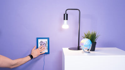
We decided to create the interactive wall in our office so that we could document the process and, more importantly, keep the interactive wall on display. The goal? To create an interactive experience where a sound is triggered by human touch; reacts when someone touches the graphic elements on the wall. The bonus? Having a smart wall on our premises so that anyone visiting our space can have first-hand interaction with the technology. Let’s break down how we did it.
Plan
The first step is to define the scope of what you’re making. You have to decide what size your wall will be, whether the display is going to respond to touch or proximity and whether the output will be video, audio, projection mapping or something else. For Ian’s wall, we decided to go for a standard 8’x4′ 15mm thick piece of plywood and focus on capacitive touch to trigger sound from each sensor. In this case, limiting the interaction to touch meant we didn’t have to worry about re-programming the software.
Once we’d defined the technical spec, it was time for the fun part. Designing the graphics and lettering. With Ian’s help, we decided on the style, typeface and illustrations. An important factor to keep in mind during the design process was the positioning of each of the twelve sensors, as well as the size and shape of the display. This is the bit where understanding the basics of sensor design becomes important. The key points for a successful design are thinking about where to position each touch point, and how to design the graphics and illustrations. It’s important to consider the position of each of the touch points because this will affect the layout of the Electrode Pads and wiring on the back of the display. It’s also important at this stage to consider the visual language, to ensure the audience knows what parts of the typographic wall are interactive.
Construct
With these parameters in mind, Ian sketched out a design for us to transfer onto the plywood. With the visuals defined, selecting the sounds was easy. We decided to trigger mp3 tracks from the Touch Board which meant loading the sounds was as simple as loading them onto a microSD card. Because our graphics were fairly straightforward, we were able to find royalty free tracks online but had we gone for something more complex, we could have recorded our own audio, or even gone down the software route to run MIDI on the Touch Board.
With the visuals and audio under our belt, it was time for the build! The first thing we did was paint the plywood white to give it more of a ‘wall’ look. To transfer Ian’s design onto the wall, we projected the hand-lettered design onto it and Ian traced it out with a pencil. Then we got out the 1-litre Electric Paint and painted the graphics onto the wall. Once the paint dried, we sprayed the graphics with a clear coat of sealing spray to keep the Electric Paint from smudging, and to give the display some protection from the elements over its lifetime.


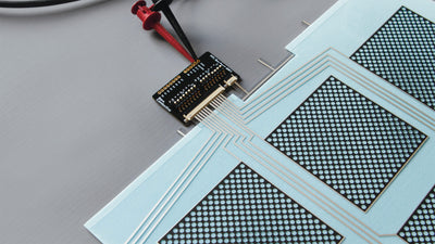
The Interactive Wall Kit is packed with the tools and techniques needed to build and troubleshoot an interactive display, so you can get from static to smart walls in no time. To begin, we drilled a hole through each of the graphics that we wanted to turn into a sensor. We used a countersink drill bit so that our mounting screws would lie flush with the surface of our wall display. Next, we attached the Touch Board, Electrode Pads, and Electrode Shield to the back of the wall using the self-tapping screws. With all the hardware in place, it was time for the wiring.
While developing the Interactive Wall Kit, one of the key takeaways from our community was the importance of a quick and straightforward way to connect their Touch Board and sensors. This, and the importance of producing a reliable, and easy-to-troubleshoot display were key in the development of this product. Enter the shielded cable. We specifically sourced these 5m long wires so that connecting between our Electrode Shield and Pads is as easy as plugging in an audio jack. Don’t be deceived, these cables do much more than allow for a quick connection. They have a unique shielding which means they can be used to create a large scale interactive display using our capacitive technology with little to now interference. Any other cable will simply behave like a long thin sensor all the way from Shield to Pad.
Finesse
As anyone who’s ever wired 60 metres worth of cable will know, tidy wiring will save hours of troubleshooting if anything does go wrong. Taking the time to finesse and neaten the wires and connections is time well spent. This is why we were careful to use the cable management clips and cable markers while connecting up the back of Ian’s interactive display. With all the cables and sensors connected, it was time to test the wall.
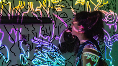
After a couple of months of product development and a two day build, you can imagine the excitement as we prepared to turn on the Touch Board and test the interactive typography wall. We switched on the board and touched the first Sensor pad, then another, until we triggered all twelve sensors. Success! To our amazement (and delight) all the sensors triggered on the first go. Ian’s typographic wall was live and ready!
If you’re looking for more ideas, here’s a list with a few of our top community interactive walls and the making process.
We’d love to see what you’ll make with the Interactive Wall Kit.
If you’d like to see your project on our blog, email us at: info@bareconductive.com
Stay connected with Bare Conductive. Follow, like and comment on Facebook, Twitter & Instagram.