How To Turn On External LEDs With The Touch Board

Add light effects to your project with external LEDs controlled by the Touch Board's sensors
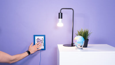
LEDs are handy for any technical project, so we have created this tutorial to explain how to connect LEDs to the Touch Board. We'll show you how to use the Touch Board's sensors to control an LED's state. Now you'll be able to trigger not just sound, but light too!
We love it when you share your projects! Post your project on Instagram, YouTube, or Twitter, and make sure to tag @bareconductive or use #bareconductive. You can also send your videos and photos to info@bareconductive.com so we can post them on our site for the world to see.
You will need:
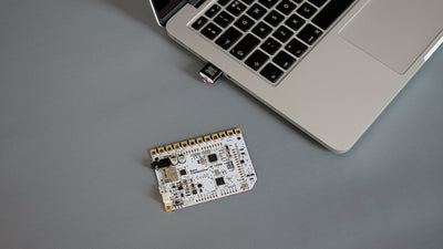
- 1 x Touch Board
- 1 x USB Micro B to USB A or USB C (depending on your computer's USB port type)
- 1 x Computer running Mac OS, Windows, or Linux
- Headers
- LED
- Jumper Wires
- Breadboard
- 270Ω resistor
Step 1 Set-up the Touch Board
If you haven't set up the Touch Board yet, please do so now by following this tutorial.
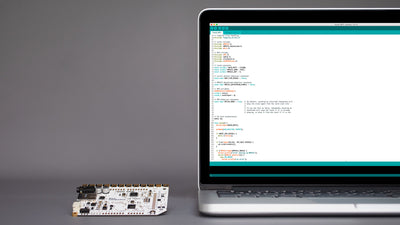
We are going to use the "touch_mp3_with_leds.ino" sketch. Select the sketch from the Sketchbook and hit upload.
Step 2 Solder headers
This next step is optional – soldering the headers onto the Touch Board. If you haven't soldered headers before, we recommend reading the articles from Sparkfun here. Alternatively, you can insert the jumper wires directly into the Touch Board's pins.
Step 3 Connect LED and resistor to breadboard
Now it is time to work on the breadboard. First, insert your 270Ω resistor between two numbered rows. We are using a 270Ω resistor; you can use other resistors, but they should be in the 220Ω – 470Ω range. Then have a look at your LED. You can see that one leg is longer than the other. This is the positive leg and you need to stick it in the same row as one end of the resistor. The shorter leg, which is the negative leg, should be inserted into the row marked with the "–" sign.
Connect one end of the red jumper wire to the free end of the resistor and one end of the blue jumper wire to the row marked with a "-". Your breadboard should look similar to the images on the right.


Step 4 Connect Touch Board to breadboard
When you are done with the breadboard, connect the blue jumper wire to GND pin on the Touch Board and the red jumper wire to pin A5. It should look like the image on the right: pin A5 is connected to the resistor and the GND pin to the LED.

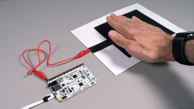
Step 5 Turn it on and touch the electrode
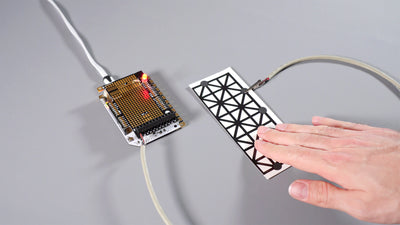
Connect the board to power and touch electrode 11. It should now light up your LED! And that's how easy it is to light up an LED with the Touch Board.
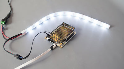
Have a closer look at line 97 in the "touch_mp3_with_leds" code. All the pins in this array, so 0, 1 10, 11, etc., are the pins that have been mapped to the electrodes. In this example, we connected an LED to A5 and turned it on with electrode E11, but you can also connect an LED to pin 0 and turn it on with electrode E0. You can also connect more than one LED as we did in the image on the right.