How to Set Up the Electrode Shield

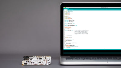
The Electrode Shield is an essential component of the Interactive Wall Kit. The shield allows you to quickly connect the Electrode Pads to the Touch Board with shielded cables and provides a prototyping area to solder more electronics to it. Attach the shield to the Touch Board and connect the Electrode Pads to the shield to set-up your interactive wall. Also, make sure to set up your Touch Board with the Arduino IDE before you begin.
We love it when you share your projects! Post your project on Instagram, YouTube, or Twitter, and make sure to tag @bareconductive or use #bareconductive. You can also send your videos and photos to info@bareconductive.com so we can post them on our site for the world to see.
Attach the Electrode Shield to the Touch Board
First, you need to attach the Electrode Shield to the Touch Board. Make sure that the Touch Board is not powered and to carefully align the headers on all three sides.
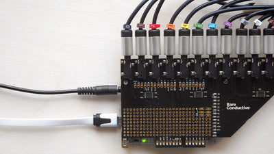
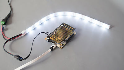
Connect the cables to the Touch Board
When the shield is sitting securely on top of the Touch Board, insert one of the cables into one of the audio jack on the shield. Then, insert the USB cable to Touch Board, and the other end to a power source.
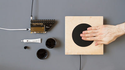
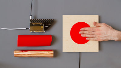
Connect the shielded cable to the Electrode Pad
Insert the other end of the shielded cable into the Electrode Pad.
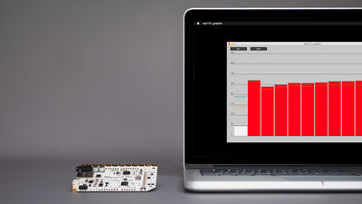
Test the Electrode Shield
Now, plug in either headphones or speakers into the Touch Board and turn the Touch Board on. Wait for the red light to stop flashing. Touch the test point on the Electrode Pad. You should now be able to hear the Touch Board Audio Guide.
You can connect up to 12 pads to the shield with the shielded cable.
If you are experiencing any issues drop us an email at info@bareconductive.com.