Interactive Wall Kit:
Get Started
Welcome to the Interactive Wall Kit
We’ve seen and built many interactive walls in our time. In this kit, we are transferring all our knowledge to you. We’ve carefully gathered a collection of the tools, resources, tips and tricks you need to make the process as easy and stress-free as possible. No searching for the right screws, no looking for the right tutorial. They’re already here ready for you. All you need to do is add your creative touch.
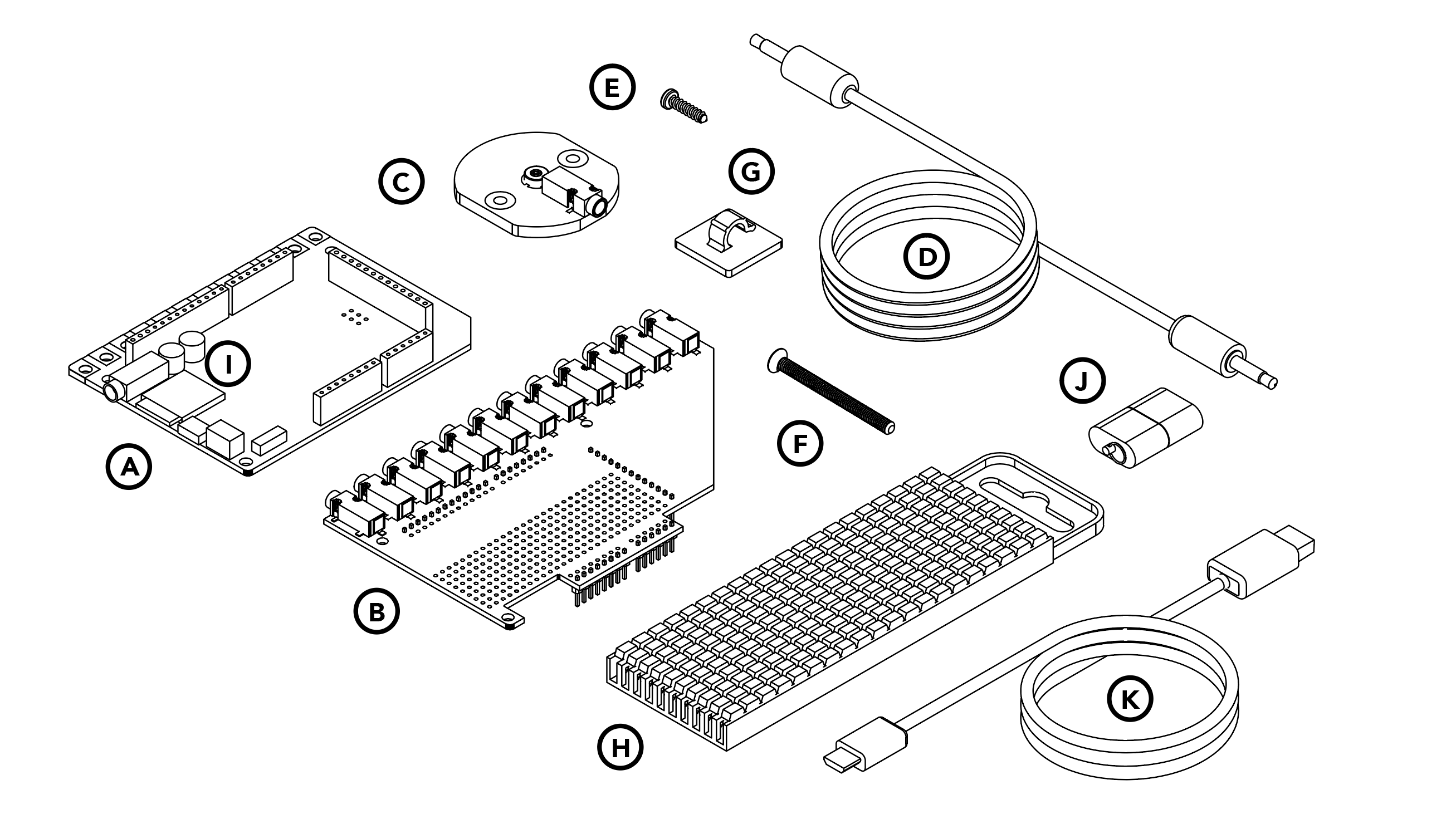
Get to know your kit
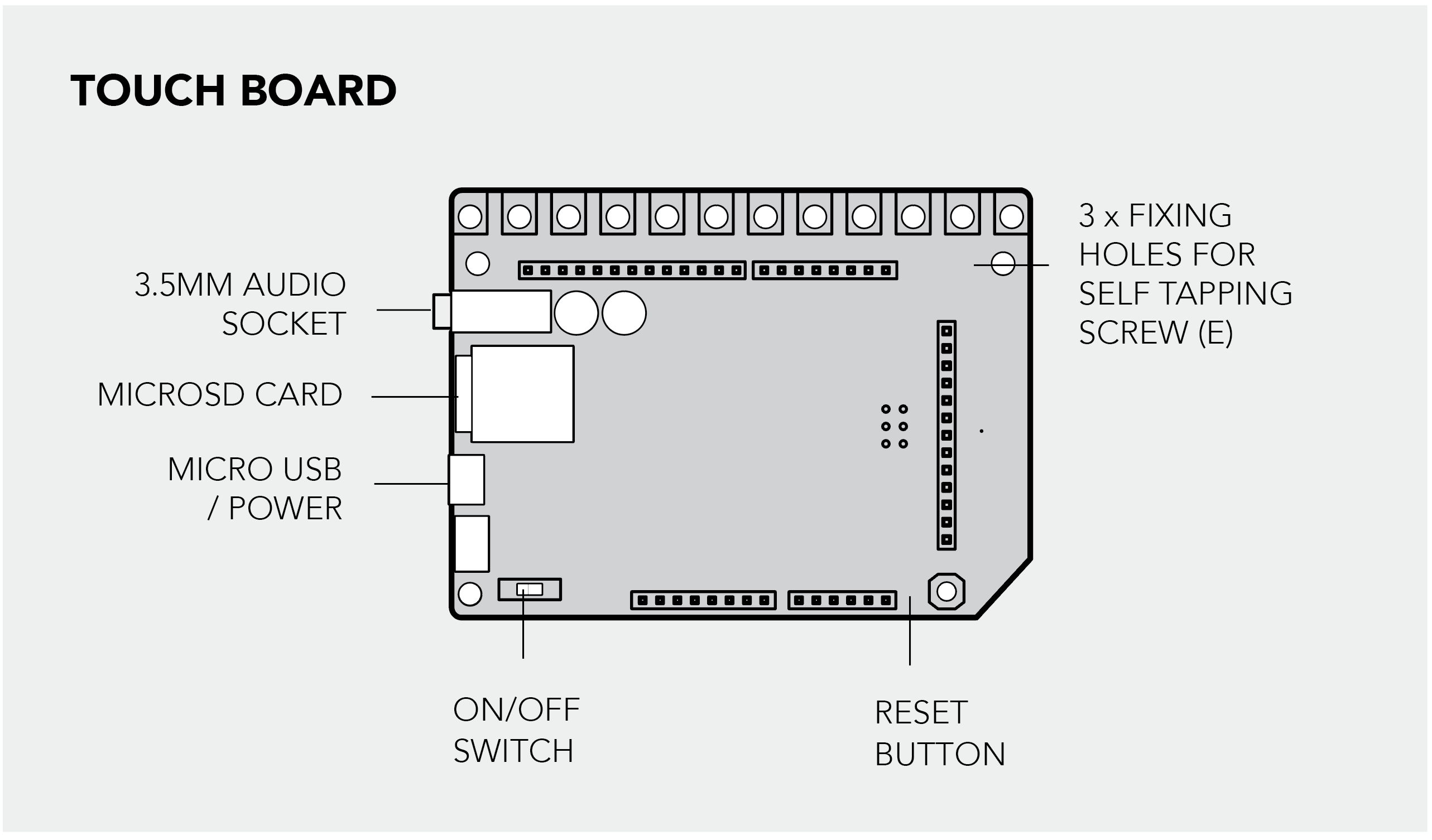
A. Touch Board with pre-soldered headers x1
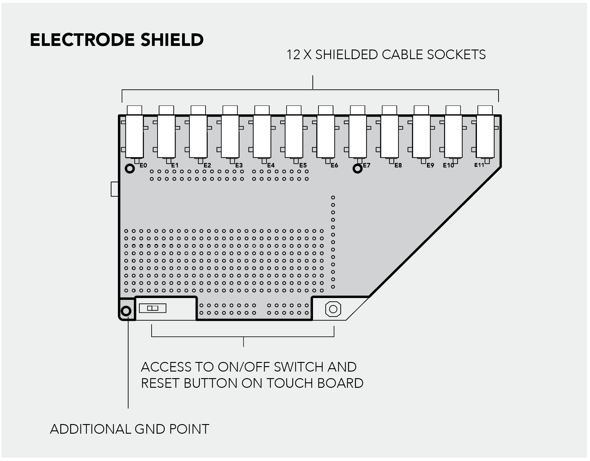
B. Electrode Shield x1
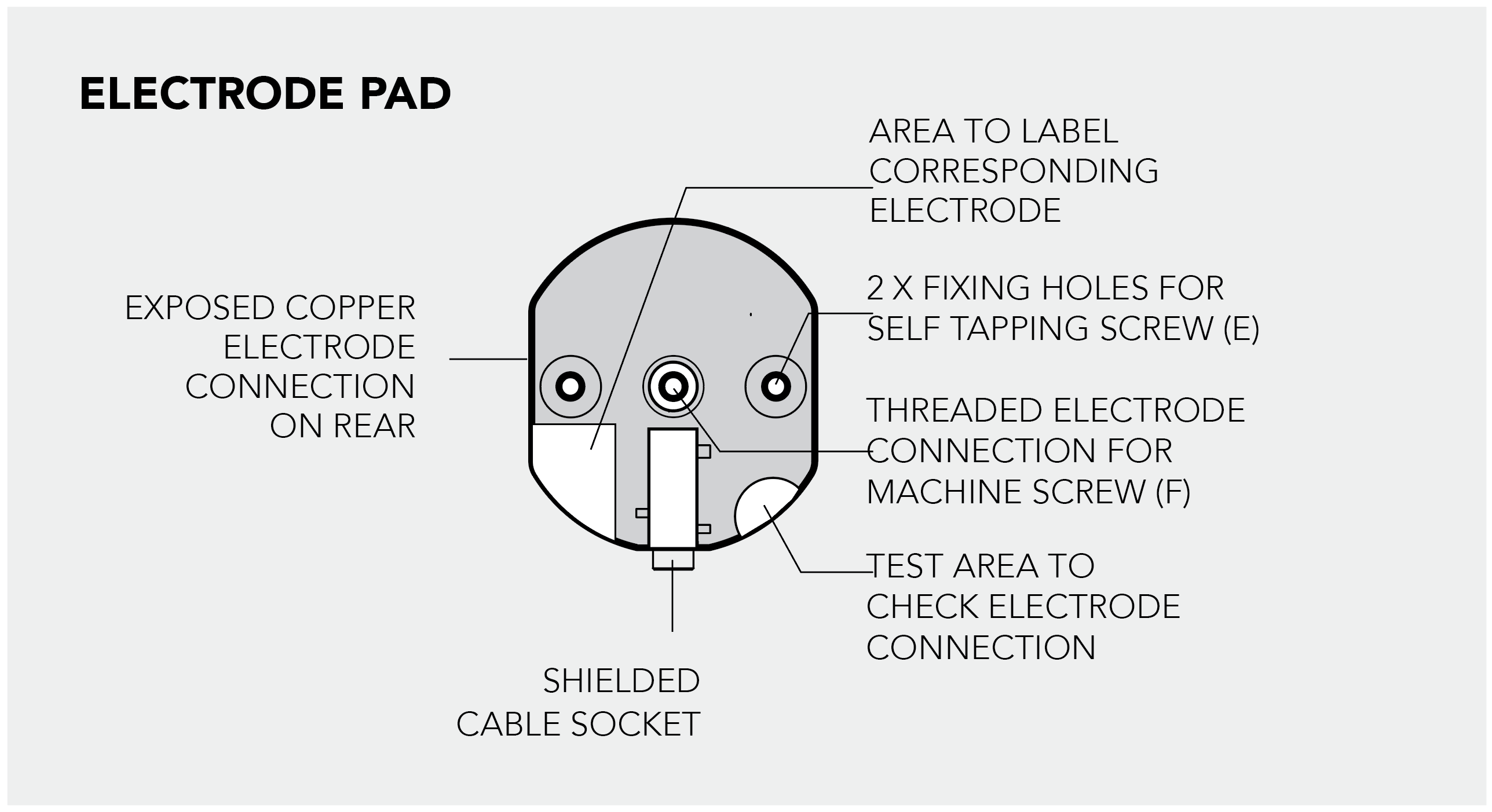
C. Electrode Pads x12
D. Shielded Cable, 5m, 3.5mm Jack Plug-Plug x12
E. Self Tapping Screw No.4 x 9.5mm x30
F. M3 Machine Screw x 30mm x12
G. Cable Management Clips x50
H. Cable Marking Set x1
I. microSD Card x1
J. microSD Card Reader x1
K. Micro USB Cable x1
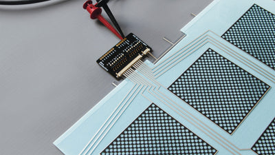
Set Up the Touch Board with the Electrode Shield
The Electrode Shield is an essential component of the Interactive Wall Kit. The shield allows you to quickly connect the Electrode Pads to the Touch Board with shielded cables and provides a prototyping area to solder more electronics to it. Attach the shield to the Touch Board and connect the Electrode Pads to the shield to set-up your interactive wall. Also, make sure to set up your Touch Board with the Arduino IDE before you begin.
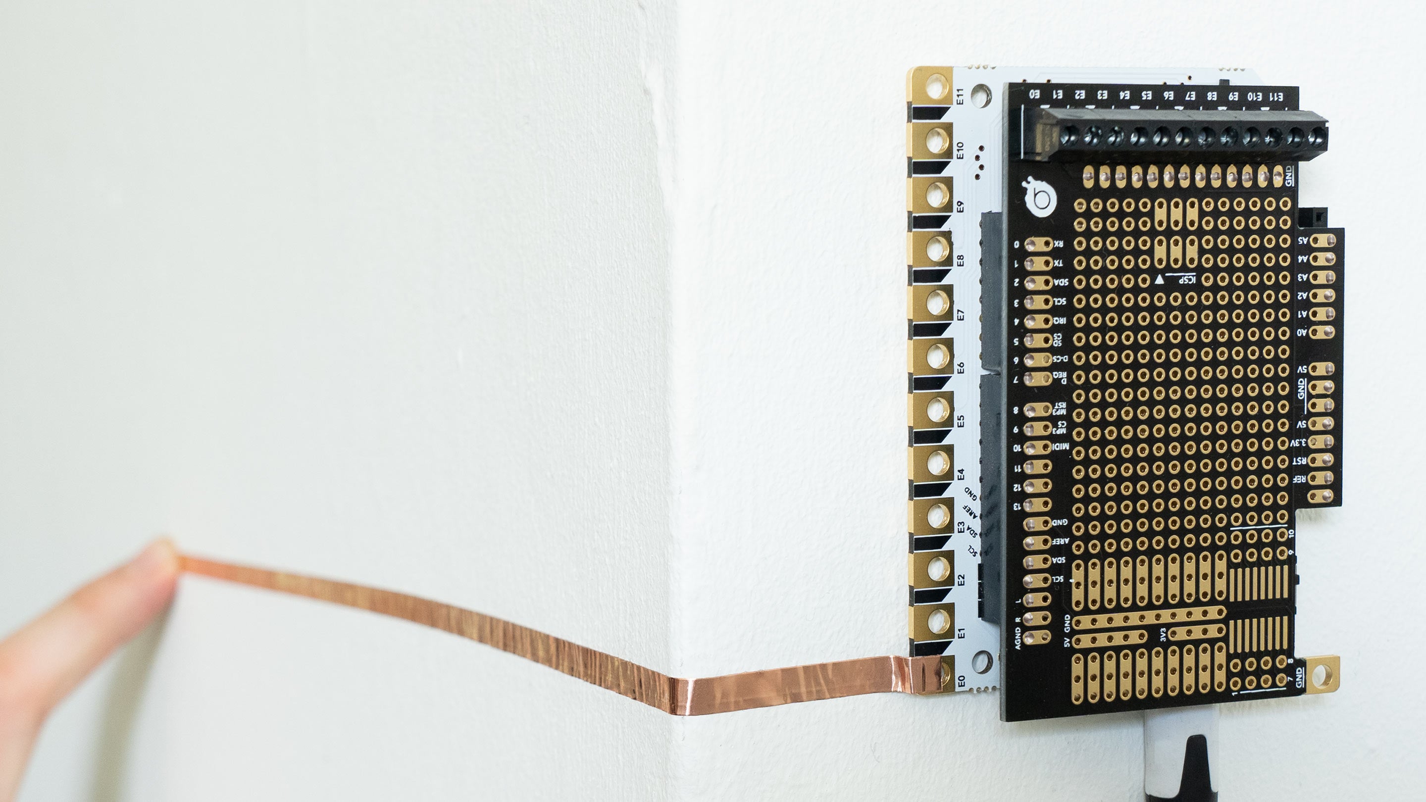
1. Attach the Electrode Shield to the Touch Board
First, you need to attach the Electrode Shield to the Touch Board. Make sure that the Touch Board is not powered and to carefully align the headers on all three sides.
2. Connect the cables to the Touch Board
When the shield is sitting securely on top of the Touch Board, insert one of the cables into one of the audio jack on the shield. Then, insert the USB cable to Touch Board, and the other end to a power source.
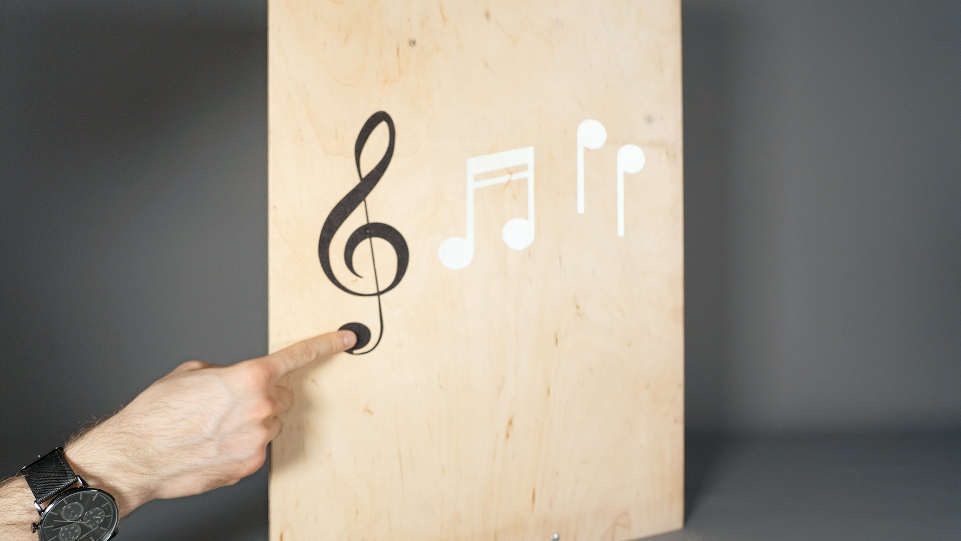
3. Touch the electrodes
Now, touch the electrode on the upper left-hand corner of your board. If everything is working, you should hear the first of twelve audio tracks that we pre-loaded to help you get started!
The electrodes are the twelve golden squares that run along the top edge of your Touch Board. They are numbered E0 to E11.
Listen to the audio guide to find out more about the Touch Board and its different features. Once you've explored the audio guide, you're ready to upload your own selection of sounds or change the code of the board!
4. Test the Electrode Shield
Now, plug in either headphones or speakers into the Touch Board and turn the Touch Board on. Wait for the red light to stop flashing. Touch the test point on the Electrode Pad. You should now be able to hear the Touch Board Audio Guide.You can connect up to 12 pads to the shield with the shielded cable.

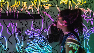
Build An
Interactive Sound Wall
Learn how to build an interactive sound wall or interactive sound mural with the Interactive Wall Kit using Electric Paint. Find out more here.
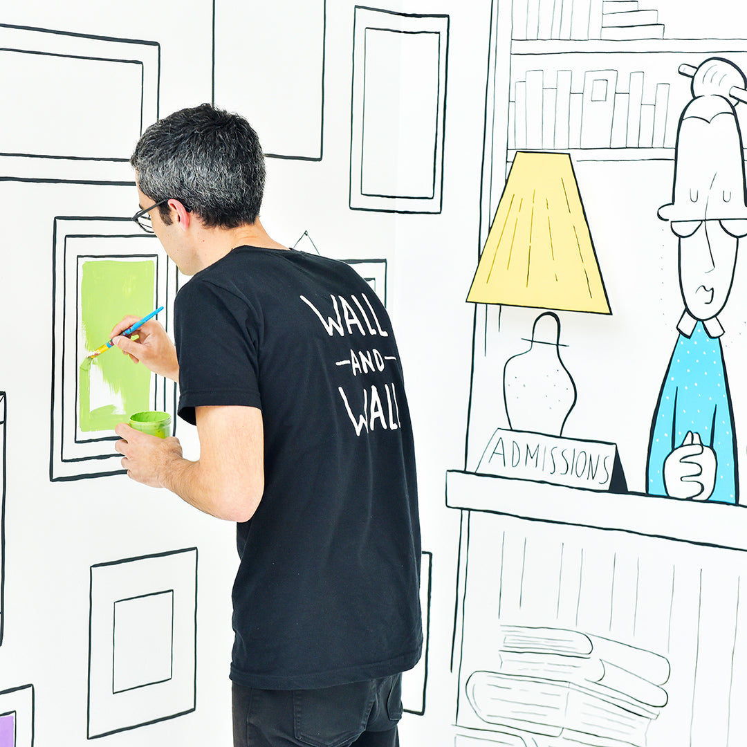
Build An Interactive
Projection Mapping Installation
Create interactive projection mapping installations with the Interactive Wall Kit. Find out more here.
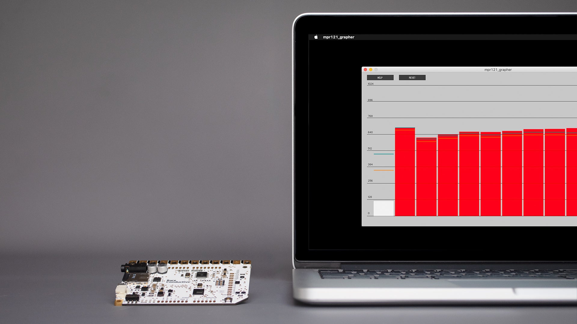
Visualise The Sensors
Sometimes it helps to visualise the sensors when you need to troubleshoot the Touch Board. Find out more here.
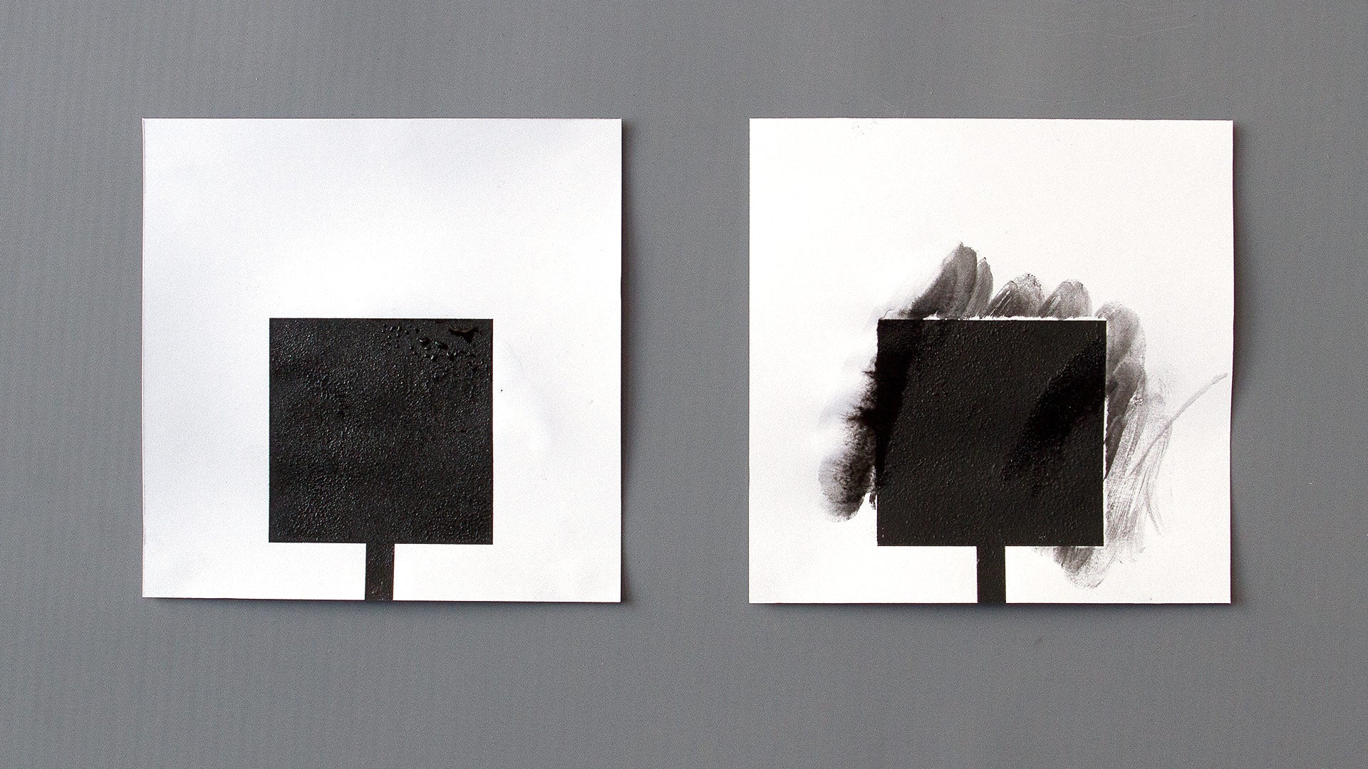
Seal Electric Paint
In order to prevent Electric Paint from smudging or cracking, we recommend sealing the paint Find out more here.
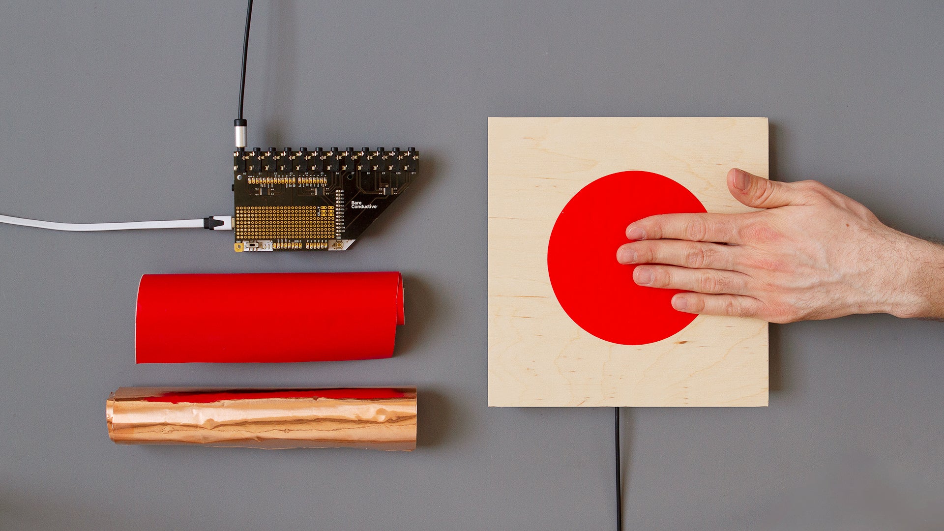
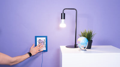
Create Proximity Sensors
Integrate touchless interaction into any interactive wall design. Find out more here.
Technical Resources
You can find all the resources for the Touch Board and Electric Paint in Product Resources page.
Product Resources